
Site Survey
Existing feature mapping — a measured record of what is already there
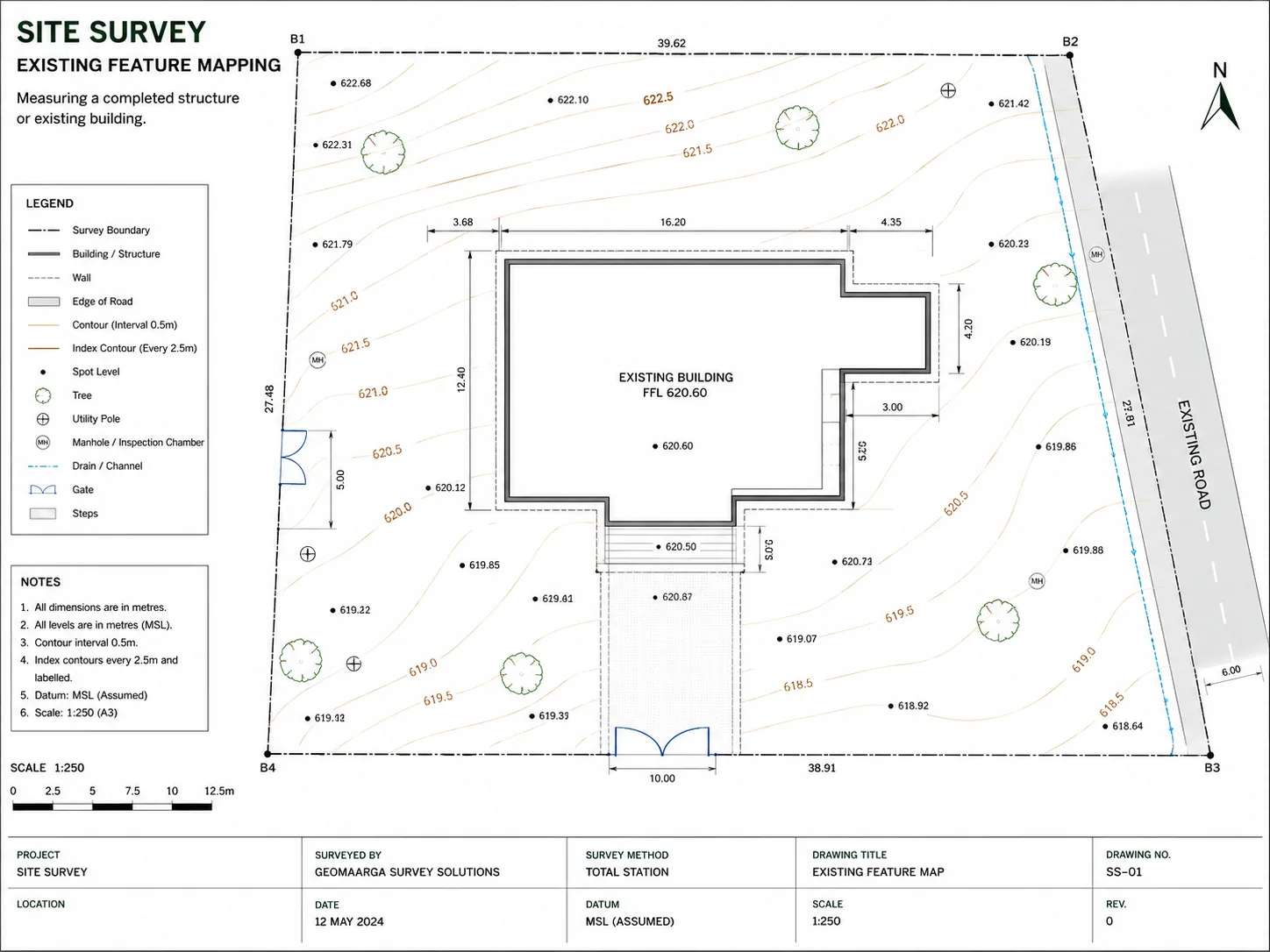
Buildings, compound walls, roads, drains, poles, trees and visible services, all located and drawn to scale. So your design starts from what is actually on the site, not from an old drawing or somebody's memory.
What you get
Agreed in the quotation before we mobilise. An existing feature survey normally delivers:
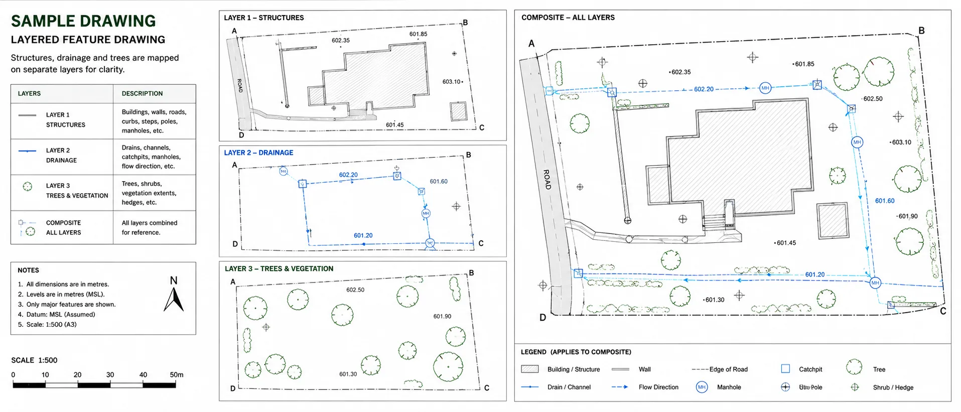
- CAD drawing in DWG and DXF, layered by feature type
- PDF plan at an agreed scale, ready to issue and print
- Spot levels at the points that matter — thresholds, road edges, drain inverts
- Tree schedule with number, girth and canopy spread, where trees are included
- Coordinate schedule of surveyed points in CSV or Excel
- Site photographs keyed to the drawing, so features can be checked later
- Survey report stating method, instruments, coordinate system and accuracy
What we map
Scope is agreed before the team mobilises, because recording more than the design needs costs time and money. A typical survey covers:
- Structures — buildings, plinths, steps, ramps, columns, canopies
- Boundaries and walls — compound walls, fences, gates, retaining walls
- Hard surfaces — roads, kerbs, footpaths, paving, parking bays
- Drainage — open drains, chambers, inlets, and invert levels where a cover lifts safely
- Visible services — poles, transformers, meter boxes, valve and manhole covers
- Trees and vegetation — individual trees with girth and canopy, hedges, planted areas
- Water features — wells, sumps, tanks, nalas and their banks
- Site context — access points, abutting road edges, neighbouring plinths
Is this the survey you need?
This sits alongside the two level-based surveys rather than replacing them. The honest comparison:
| Feature mapping | Contour | Topographic | |
|---|---|---|---|
| Buildings and structures | Yes | No | Yes |
| Trees, poles, drains | Yes | No | Yes |
| Spot levels at key points | Yes | Yes | Yes |
| Levels across a grid | No | Yes | Yes |
| Contour lines | No | Yes | Yes |
| Plot extent from documents | On request | No | Yes |
Choose feature mapping when the site is broadly flat or the levels are not the problem, and what you need to know is what is in the way.
Choose a topographic survey when you need both — features and the shape of the ground. For most development projects this is the honest answer, and it costs less than commissioning two surveys separately.

What we can and cannot see
Worth being clear about, because it is the most common misunderstanding on this kind of survey.
We measure what is visible and accessible. A manhole cover is recorded, and its invert level taken if the cover lifts safely. What runs between two chambers underground is not something a survey instrument can see. Tracing buried pipes and cables is a separate exercise using detection equipment, which we can arrange when a project needs it.
We will not draw an assumed pipe route as though it had been measured. A line on a drawing looks equally confident whether it was surveyed or guessed, and the difference only emerges when somebody digs.
Accuracy you can expect
| Method | Horizontal accuracy | Used where |
|---|---|---|
| Total station on adjusted traverse | ±10–20 mm | Built-up sites, indoors, under canopy — most of this work |
| Total station, reflectorless | ±(3 mm + 2 ppm) on the measurement | Building faces, parapets and points that cannot be reached |
| DGPS, RTK | ±8 mm + 1 ppm | Open sites and the outer parts of large plots |
Figures are typical achievable tolerances for survey-grade equipment under reasonable field conditions, not a contractual guarantee. The accuracy actually achieved on your site is stated in the survey report.
When you need one
- Before extending or altering an existing building
- Before redeveloping a plot that already has structures on it
- When planning around trees that have to be retained
- Before designing services, so new routes avoid what is already there
- When an old drawing no longer matches what is on site
- Before buying a developed property, to record what is included
- For approval submissions that require existing conditions shown
Typical applications
- Building extension and alterationExisting structure measured so the new work fits what is actually built
- Redevelopment of an occupied plotEverything standing recorded before demolition or phasing is planned
- Tree retention planningNumbered tree schedule with girth and canopy for the design team
- Industrial plant expansionExisting roads, drains, plinths and services mapped for new build
- Services and utility designVisible chambers, poles and covers located so new routes avoid them
- Refurbishment and change of useInternal walls, columns, openings and floor levels measured
Related reading
Most of this work is total station work, because the sites that have things standing on them are exactly the sites where surrounding walls and buildings block the sky that satellite equipment needs.
- Total station or DGPS — how we choose the method
- GPS vs DGPS — the differential principle
- Why satellite levels are not sea levels
Related services
How we work
How we map existing features
-
Agree the scope
Which features matter, whether trees and internal spaces are included, and what CAD layer standard your team works to.
-
Establish control
Reference points set around the site and closed, so features measured from different set-ups all agree with each other.
-
Walk and record
Features picked up and coded as they are measured, with photographs taken as we go so anything unclear can be checked at drafting.
-
Open what can be opened
Chamber and manhole covers lifted where it is safe, invert levels taken, and anything inaccessible noted on the drawing rather than assumed.
-
Check from second control
Selected features re-observed from a different station. Where the two disagree beyond tolerance we re-measure rather than average.
-
Draft in layers and issue
Drawing built up layer by layer, tree schedule compiled, photographs keyed to the plan, and the report issued alongside.
Questions
Existing feature mapping FAQs
A topographic survey covers everything: features, levels, contours and plot extent together. Existing feature mapping concentrates on what is standing on the site and where it sits in plan. Levels are taken where they matter — thresholds, road edges, drain inverts — but the site is not gridded for contours. If your design depends on how the ground falls, ask for the topographic survey. If it depends on what is in the way, this is the one.
Yes, at the points where a designer needs them: floor and threshold levels, plinth heights, road and kerb levels at the entrance, drain and chamber inverts where a cover can be safely lifted. What you do not get is a grid of levels across the whole site or contour lines drawn from them. Those come with a contour or topographic survey.
We record what is visible and measurable at the surface — manholes, chambers, valve covers, inspection covers, poles, transformers and inlets — and take invert levels where a chamber can be safely opened. Tracing buried pipes and cables between those points is a separate utility detection exercise using different equipment, which we can arrange if the project needs it. We will not guess a route and draw it as though it were measured.
Yes. Each tree is located, numbered on the drawing and listed with its girth and canopy spread, and species where it can be identified on site. This is what a design team needs to decide what can be retained and what has to be worked around. If a schedule has to be submitted to an authority, tell us the format they expect and we will match it.
Yes. Internal walls, columns, openings, floor levels and headroom can all be measured, which is common before a refurbishment or a change of use. Satellite equipment does not work indoors, so this is total station work, and it takes longer than an open site because every room needs its own set-up and a line of sight back to control.
By layer, so your team can switch off what they do not need. Structures, boundaries, hard surfaces, drainage, services, vegetation and levels each sit on their own layer, named consistently. If your practice has a layer standard or a CAD template, send it with the enquiry and we will deliver in it rather than leaving you to reorganise the file.