
Construction Survey
Grid setting out — the reference your whole frame is built to
The grid lines your drawings call A, B, C and 1, 2, 3, marked accurately on site and re-established at every floor. Every column, beam and wall position is measured from them, so the grid has to be right before anything else can be.
On site this work is usually called grid marking or centre line marking. It is the same job.

What you get
Agreed in the quotation before we mobilise. Grid setting out normally delivers:
- Grid lines marked on the slab in both directions, labelled to match your drawing
- Grid intersections marked, positioned clear of shuttering and reinforcement
- Offset marks outside the working area, so a disturbed line can be recovered
- Diagonal check results recorded and reported, not just performed
- Coordinate schedule for every intersection, in CSV or Excel
- Floor level confirmed and marked against the project datum
- Setting-out report stating method, control used and accuracy achieved
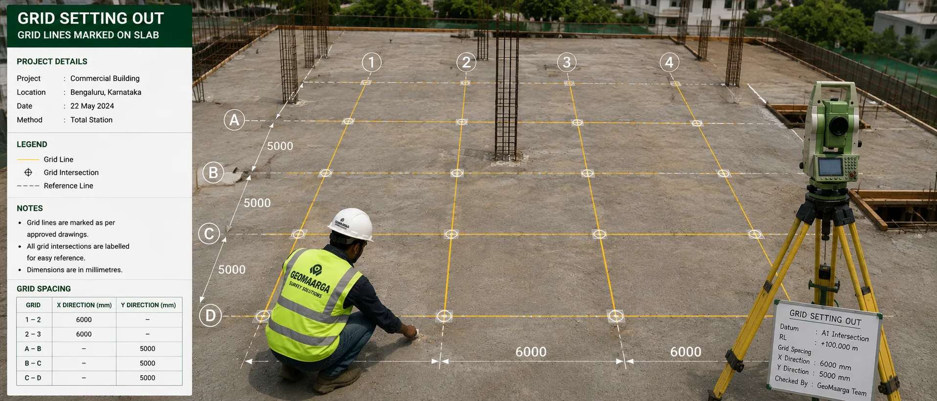
Grid setting out is not the same as layout
The two get confused, and they do different jobs.
Layout survey puts the building in the right place on your plot — footprint, setbacks, orientation. It happens once, before excavation.
Grid setting out establishes the structural reference lines inside that footprint. It happens again on every floor as the frame rises, because each new slab needs the grid marked on it before columns can be positioned.
Most projects need both. There is a practical reason to have the same team do them: the grid is derived from the control established during layout, so nothing has to be re-derived or reconciled between two sets of records.
Every dimension can be right and the grid still not square
Measuring along the grid lines confirms the spacing. It does not confirm the shape. A rectangle with every side correct can still be leaning — a parallelogram, not a rectangle — and nothing you measure along the lines will reveal it.
The diagonals do. If the two diagonals of a bay are not equal, the bay is not square, and every column set on that grid drifts further out of position towards the far corner of the building.
We check diagonals before the grid is released for use, and we report the figures rather than simply confirming we did it. It takes a few minutes and it catches an error that spacing measurements cannot see.
Carrying the grid up the building
This is where the difference between a good grid and a bad one shows, usually around the fifth or sixth floor.
The wrong way is to copy the grid from the floor below. It seems reasonable and it is quick, but each floor then inherits the error of the one beneath it. Small errors compound. By a few floors up, columns no longer line up through the building, and by the time anyone notices, the fix is expensive.
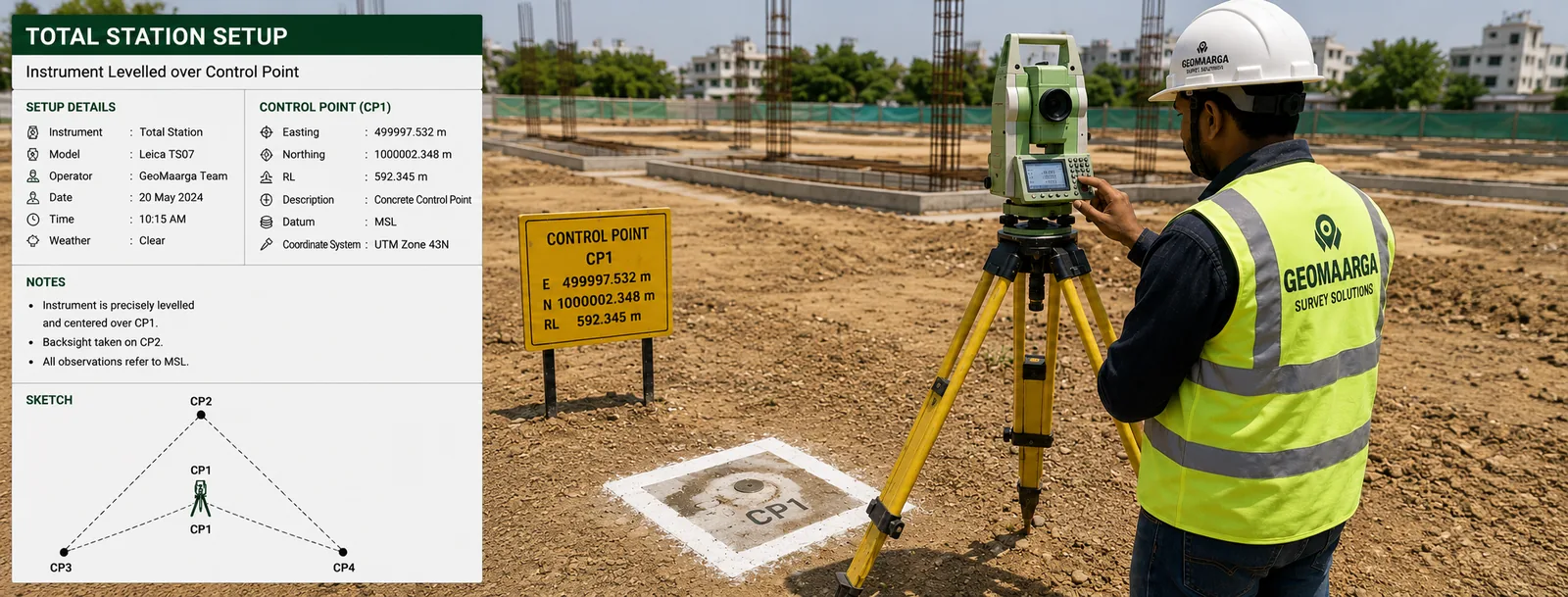
We re-establish each floor against the original ground-level control — the same reference every time, so no floor depends on the accuracy of another. Where the structure blocks a direct line of sight, positions are carried up through a checked transfer rather than assumed from the slab below.
Accuracy you can expect
| Measurement | Accuracy | Notes |
|---|---|---|
| Grid intersection position | ±10–20 mm | From control closed to 1:10,000 or better |
| Diagonal check | Measured and reported | Grid not released for use until it passes |
| Floor level | ±5–10 mm | Closed level run from the project datum |
| Angular accuracy | ±3 seconds of arc | About 1.5 mm of lateral error at 100 m |
Figures are typical achievable tolerances for survey-grade equipment under reasonable field conditions, not a contractual guarantee. The tolerance your structure actually requires is set by your structural engineer and the relevant code — tell us the figure you are working to and we will confirm whether our method meets it before you appoint us.
When you need this
- Before column positions can be marked on any framed structure
- At every floor level as the frame rises
- When a building has long spans, where small angular error becomes large displacement
- When multiple blocks must align with each other across a site
- Before precast or steel elements arrive, since they cannot be adjusted on site
- When something further up the building is not lining up and you need to know why
Typical applications
- Apartment and commercial framesGrid marked and re-established floor by floor as the structure rises
- Industrial sheds and warehousesLong spans where a small angular error shows badly at the far end
- Steel and precast structuresGrid set before fabricated elements arrive, since they cannot be trimmed on site
- Basement and podium structuresGrid carried down as well as up, tied to the same control
- Multi-block developmentsEach block on its own grid, all tied to one site framework
- Checking an inherited gridExisting marks verified against drawing and diagonal before work continues
Related reading
Grid work is total station work throughout. A part-built frame blocks most of the sky, and the tolerance required is tighter than satellite positioning delivers reliably.
- Total station or DGPS — how we choose the method
- Why satellite levels are not sea levels
- GPS vs DGPS — the differential principle
Related services
- Layout Survey — placing the building on the plot first
- Column Marking — column centres set out from this grid
- Foundation Marking — footings and pile caps
- Level Transfer — carrying the datum up the building
- Construction Monitoring — verticality and movement during the build
- As-Built Survey — what was actually constructed
- All construction survey services
How we work
How we set out a structural grid
-
Read the structural drawing
Grid spacings, labelling and any non-orthogonal lines checked against the architectural drawing before mobilising, so discrepancies surface early.
-
Work from the site control
The grid is computed from the same control established at layout stage, so the structure sits correctly on the plot as well as square to itself.
-
Set out the intersections
Grid intersections positioned and marked, with offset marks placed outside the working area where shuttering and steel will not reach them.
-
Check the diagonals
Squareness verified by diagonal measurement across each bay. The grid is not handed over for use until the diagonals agree.
-
Confirm the level
Slab level checked against the project datum by closed run, so the grid is correct in three dimensions rather than two.
-
Repeat at every floor
Each new slab set out afresh from the original control — never copied from the floor below — with the diagonal check repeated each time.
Questions
Grid setting out FAQs
Layout survey puts the building in the right place on your plot — footprint, setbacks, orientation. Grid setting out establishes the structural reference lines inside that footprint, the ones your drawings label A, B, C and 1, 2, 3. Layout is done once before excavation. The grid is re-established at every floor as the frame goes up. Most projects need both, and it is efficient to have the same team do them because the grid is derived from the control set during layout.
Because a grid can have every individual dimension correct and still not be square. Measuring along the lines only confirms spacing; measuring the diagonals confirms the geometry. If the diagonals of a rectangle do not match, the shape is a parallelogram, and every column placed on it will be progressively out of position towards the far corner. It is a quick check and it catches an error that spacing measurements cannot see.
Yes, and how it is done matters. The grid should be carried up from the original ground-level control, not copied from the floor below. Copying from the floor below means each floor inherits the error of the one under it, and by the fifth or sixth slab the drift is visible. We re-establish each floor against the same control, so no floor depends on the accuracy of another. See level transfer for the vertical side of the same problem.
Grid lines marked on the slab in both directions, with intersections and offset marks positioned clear of where shuttering and reinforcement will sit. Marks are labelled to match your drawing, so the site engineer reads the same reference the designer used. Coordinates are recorded, so a mark lost during the pour can be reinstated exactly.
Grid intersections are set out to within a few millimetres of their designed position from control closed to 1:10,000 or better, and the diagonals are checked before the grid is released for use. What tolerance your structure actually requires is set by your structural engineer and the relevant code — tell us the figure you are working to and we will confirm whether our method meets it before you appoint us.
Yes. A check survey measures the existing grid against the drawing, verifies squareness by diagonal, and reports the differences without disturbing anything. It is a sensible step if you have inherited a part-built structure, if the marks were set by someone whose method you do not know, or if something further up the building is not lining up and you want to find out why.
Yes. Grid marking, centre line marking and grid setting out all describe the same work — establishing the structural reference lines your drawing labels A, B, C and 1, 2, 3, and marking them accurately on the slab. Different site teams and different engineers use different names for it. Ask for whichever term you are used to; we will know what you mean.