
Infrastructure Survey
Utility corridor survey — mapping what is already in the ground
Existing services and constraints located and levelled within a shared corridor, in one coordinate system. So a new asset can be routed through the space that actually exists rather than the space the records imply.
Also called utility mapping, a service corridor survey or a clash survey.
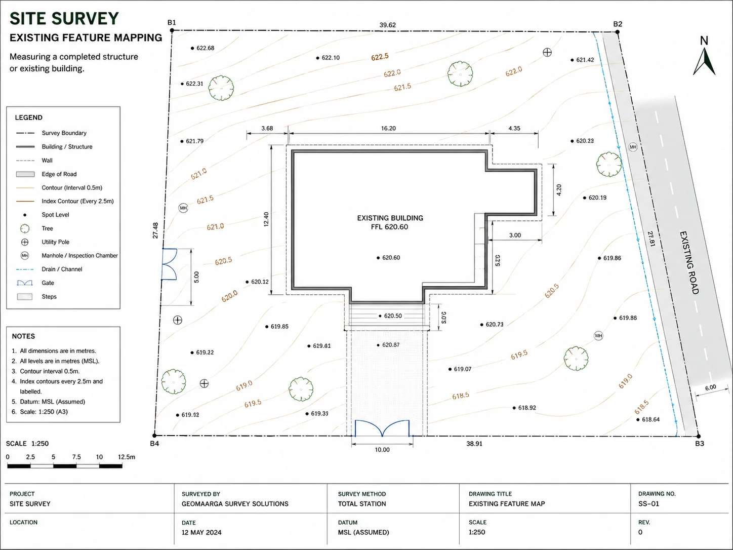
A survey measures what it can see
We locate every visible indication of a service precisely — chambers, covers, valve boxes, marker posts, poles, cabinets — and take invert levels wherever a chamber can be safely opened.
What runs between those points underground is not something a survey instrument can measure. Tracing buried cables and pipes needs detection equipment, which is a separate exercise and one we can arrange when the project warrants it.
What we will not do is draw an assumed route as though it had been measured. A line on a drawing looks equally confident whether it was surveyed or guessed, and on a utility corridor the difference is found by an excavator.
What you get
Agreed in the quotation before we mobilise. A utility corridor survey normally delivers:
- Corridor plan in DWG and DXF, layered by service type and by data source
- Every visible service feature located, with cover levels
- Invert levels and chamber detail wherever a cover can be safely lifted
- Authority record data plotted as a separate, clearly identified layer
- Physical constraints — carriageway edges, footpaths, trees, structures, boundaries
- Trial pit and exposed service positions measured where available
- Coordinate and level schedules in the coordinate system your design uses
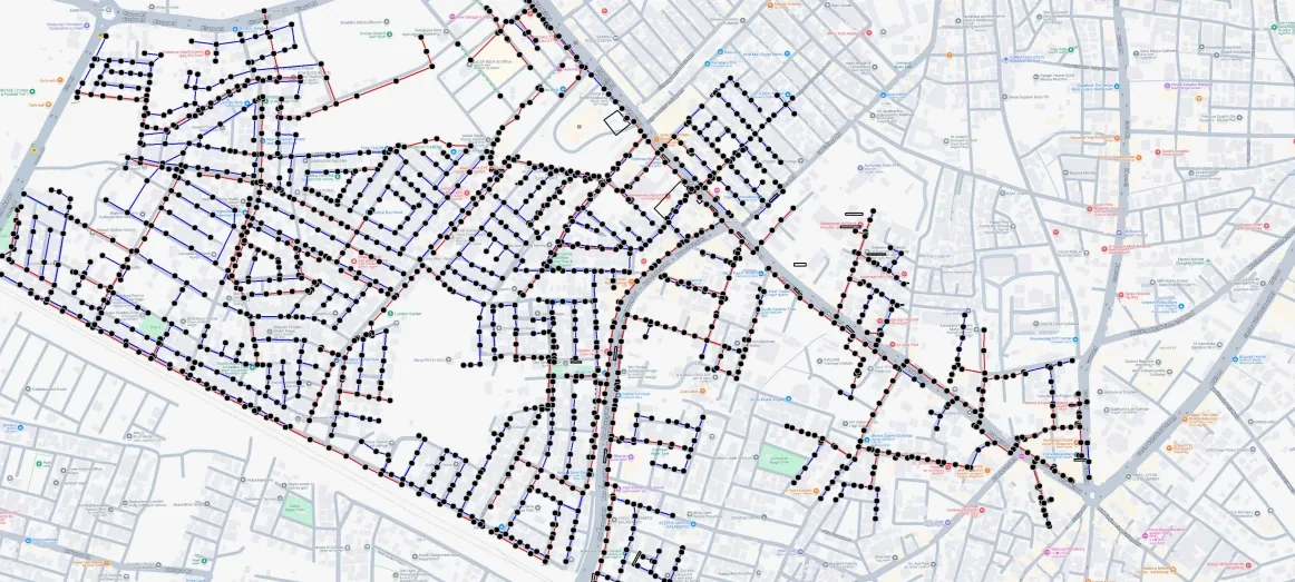
Measured and recorded data never share a layer
Record drawings from service authorities vary enormously in accuracy and age. Some are excellent. Some show a main on the wrong side of the road.
So they go on a separate, clearly identified layer — never merged into the measured survey. A record line drawn in the same style as a measured one is genuinely dangerous, because nobody downstream can tell which is which, and both get trusted equally.
Keeping them apart lets your designer weigh each appropriately: certainty where we measured it, caution where somebody else drew it.
What we record
- Chambers and manholes — position, cover level, and invert levels where they can be safely opened
- Covers and boxes — valve, inspection, meter and stopcock covers
- Markers — route marker posts, plates and painted indications
- Above-ground plant — poles, stays, transformers, feeder pillars, cabinets, lighting columns
- Exposed services — anything visible in an open trench or trial pit
- Corridor constraints — carriageway edges, footpath widths, kerbs, trees, structures, boundaries
- Levels along and across the corridor, so available depth is understood as well as plan space
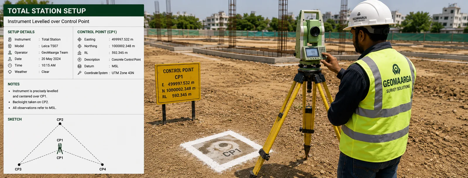
Why a narrow corridor needs more survey, not less
It seems backwards. A strip of ground a few metres wide should be the simplest thing on any project.
But a narrow corridor is exactly where clashes happen. Several authorities may hold assets in the same strip, laid at different times, to different standards, recorded on drawings that were never reconciled with each other. The space available for a new service is usually the space nobody has documented.
Measuring what is visible — accurately, and in one coordinate system — is what lets a designer see the real room rather than assume it. Half of the value here is simply that everything ends up on the same grid for the first time.
Trial pits are the best data on the job
Where a trial pit is dug or a service is exposed during other works, the position and level of what is uncovered is worth more than any record drawing — it is direct measurement of the actual asset.
Recording it properly while the excavation is open turns a one-off exposure into permanent information. It costs very little as an addition to work already happening, and it is the kind of data that stops a future project digging blind.
If your programme includes trial pitting, tell us and we will schedule around it. Measuring a pit after it has been backfilled is not possible.
Accuracy you can expect
| Measurement | Accuracy | Notes |
|---|---|---|
| Visible feature position | ±10–20 mm | Total station, typical in built-up corridors |
| Cover and invert levels | ±5–10 mm | Closed level runs from the project datum |
| Open corridor detail, RTK | ±8 mm + 1 ppm | Where the corridor is open to the sky |
| Buried route between features | Not surveyed | Requires detection; never inferred on our drawings |
Figures are typical achievable tolerances for survey-grade equipment under reasonable field conditions, not a contractual guarantee. The last row is the one that matters most: precision on the features we measure says nothing about what lies between them.
When you need this
- Before routing a new pipeline, cable or duct through an existing corridor
- Before road widening or footpath reconstruction where services will be affected
- When several authorities have assets in the same strip and nobody has one drawing
- Before trenchless crossings, where entry and exit must avoid existing plant
- When a diversion has to be designed around what is already there
- To capture trial pit and exposed service data while excavations are open
Typical applications
- New service routingCorridor mapped so a new main or cable is designed around real constraints
- Road and footpath worksExisting services located before reconstruction affects them
- Service diversionsWhat is there measured before a diversion route is designed
- Industrial and campus corridorsShared service routes within a facility mapped onto one grid
- Trial pit recordingExposed services measured while excavations are open
- Multi-authority corridorsAssets from several owners brought onto a single coordinate system
Related reading
Corridor work in built-up ground is total station work — narrow streets and adjacent buildings block the sky that satellite positioning needs, and reflected signals there are worse than no signal.
- Total station or DGPS — how we choose the method
- GPS vs DGPS — the differential principle
- Why satellite levels are not sea levels
Related services
- Pipeline Survey — routing a new main through the corridor
- Highway Survey — the road corridor above the services
- Transmission Line Survey — route profile above ground
- Industrial Plant Survey — services within a facility
- Existing Feature Mapping — the equivalent on a single site
- As-Built Survey — recording new services before backfill
- All infrastructure survey services
How we work
How we survey a utility corridor
-
Gather the records first
Whatever authority drawings you hold are collected before mobilising, so the field team knows what to look for and where the gaps are.
-
Establish control
Control set along the corridor and closed, so every feature — and every later addition — lands on one coordinate system.
-
Walk and locate
Every visible service indication measured and coded, with photographs, and anything ambiguous noted rather than guessed.
-
Open what opens safely
Chamber covers lifted where it is safe and permitted, invert levels and connections recorded, and anything that cannot be opened marked as such.
-
Capture exposures
Trial pits and services exposed by other works measured while open — the most reliable data available on this kind of job.
-
Draft on separated layers
Measured data and authority record data drawn on visibly distinct layers, so no one downstream mistakes one for the other.
Questions
Utility corridor survey FAQs
Not by survey alone, and this is the most important thing to understand before commissioning the work. A survey instrument measures what it can see. We locate every visible surface feature precisely — chambers, covers, valve boxes, marker posts, poles, cabinets — and take invert levels wherever a chamber can be safely opened. What runs between those points underground needs detection equipment, which is a separate exercise we can arrange. We will not draw an assumed route as though it were measured.
We plot them as a separate, clearly identified layer — never merged into the measured survey. Record drawings from service authorities vary enormously in accuracy and age, and a record line drawn in the same style as a measured one is dangerous, because nobody downstream can tell which is which. Keeping them apart lets your designer weigh each appropriately.
Every visible indication of a service — manholes and chambers with cover and invert levels, valve and inspection covers, marker posts and route markers, poles, stay wires, transformers, feeder pillars, cabinets, street lighting, and any exposed duct or pipe. Alongside that we record the physical constraints of the corridor: carriageway edges, footpath widths, trees, structures, boundaries and levels.
Because a narrow corridor is exactly where clashes happen. Several authorities may have assets in the same strip, laid at different times to different records, and the space available for a new one is usually the space nobody has documented. Measuring what is visible, accurately and in one coordinate system, is what lets a designer see the real room rather than assume it.
Yes, and it is the most reliable data on the whole job. Where a trial pit is dug or a service is exposed during works, we measure the actual position and level of what is uncovered. Those points are worth far more than any record drawing, and recording them properly while the excavation is open turns a one-off exposure into permanent information.
We supply the measured survey and any record data as separate layers, in the coordinate system your design is being done in, so your designer can run the clash check against their proposed route. Deciding what constitutes a clash, what clearance is required and how to resolve it are design decisions for your engineer and the asset owners involved. We provide the measurement that check depends on.