
Construction Survey
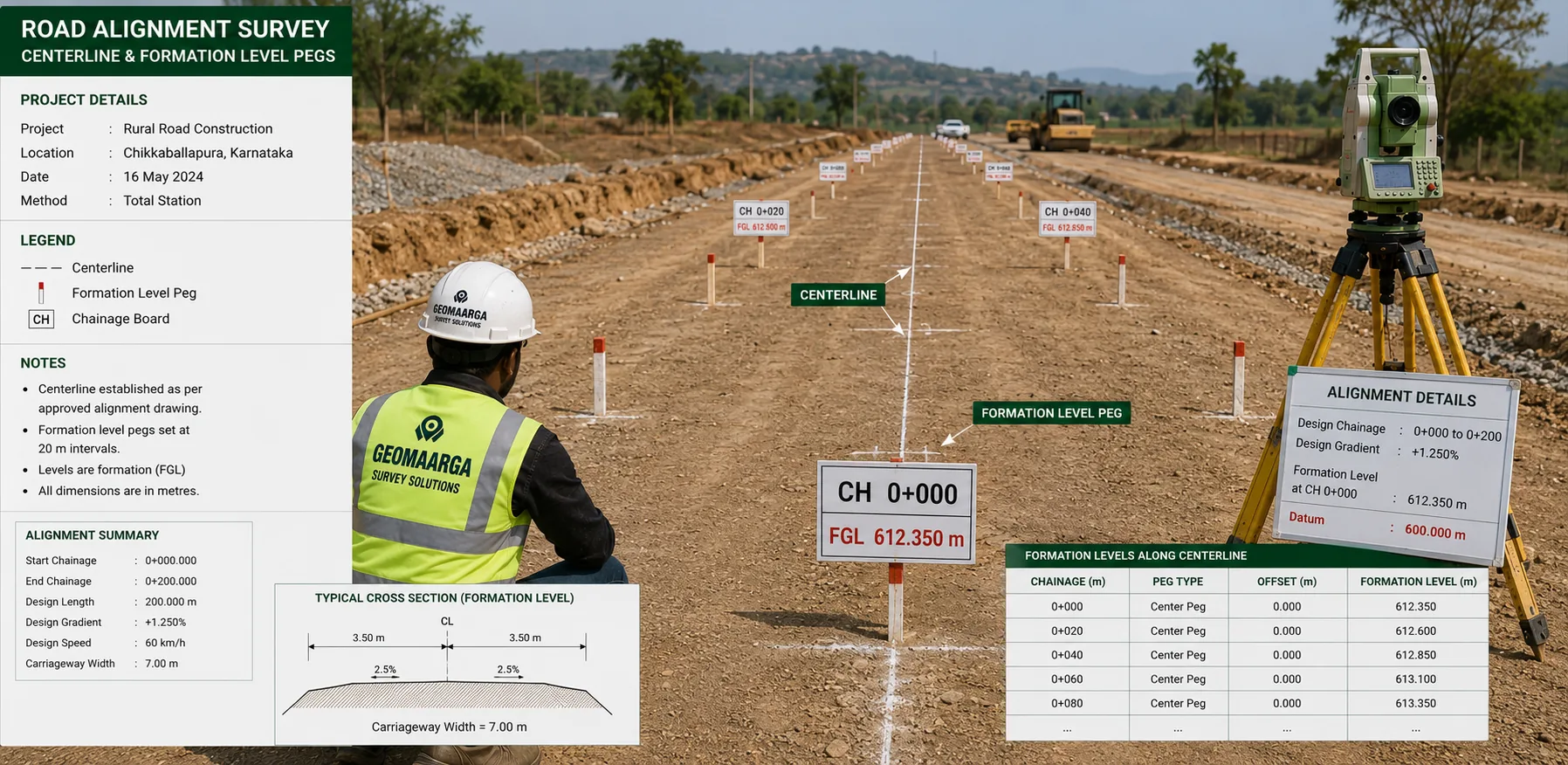
Road alignment — the line and the levels, set out at chainage
Centreline, curves, formation levels, camber and kerb lines for internal and access roads. Set out so the road runs where it should and drains the way it was designed to.
On site this work is usually called centre line marking or road marking. It is the same job.

What you get
Agreed in the quotation before we mobilise. Road alignment setting out normally delivers:
- Centreline pegged at chainage, with intervals closed up through curves
- Curve setting out — tangent points, radius points and intermediate chainages
- Formation level pegs at chainage, with cross-section levels for the machine
- Camber or crossfall marked, so the surface drains as designed
- Kerb lines set as offsets from the centreline, with levels along the top
- Offset pegs clear of the working width, so the line survives the earthwork
- Chainage and coordinate schedule in CSV or Excel, plus a setting-out report
Chainage — one number everyone can use
Chainage is distance measured along the centreline from a fixed start point. It lets any position on the road be described as a single number instead of a pair of coordinates.
That sounds like a small thing and it is the reason road work stays coordinated. The design, the level sheet, the earthwork claim, the site instruction and the drainage layout all refer to the same chainage. When somebody says the formation is low at 240, everyone knows exactly which piece of road that is — no measuring back from a gate, no arguing about which bend was meant.
A curve pegged too far apart is a series of straight lines
Curves are set out by computing coordinates along the design geometry and marking points at chainage intervals. Peg them too far apart and the machine simply runs straight between the pegs — so what gets built is a chain of short straights with kinks at each peg.
It looks acceptable while the earthwork is open, and it is obvious once the kerbs are laid and the road is surfaced. By then it is not something you fix cheaply.
How close the intervals need to be is set by the radius, not by how quickly the pegs can be placed. A tight radius gets closer intervals. We work that out from the geometry rather than pacing it out.
The levels are the harder part
Getting a road on line is straightforward. Getting it to the right level, with the right fall, is where roads actually fail.
A road built on line but not to level does not drain. Water sits on it, finds the edges, gets into the sub-base, and the surface fails from underneath. That is the problem that shows up in the first monsoon and gets blamed on the surfacing.
So the level work runs through the whole job:
- Formation level pegged at chainage, with cross-section levels so the machine has a reference across the width, not just along the middle
- Camber or crossfall marked, so the surface sheds water to the intended side
- Layer thickness checked as the pavement is built up, where included
- Kerb levels along the top, so the kerb is laid to a grade rather than followed by eye
- Gully and invert levels set from the same control, so the drainage and the surface agree
Accuracy you can expect
| Measurement | Accuracy | Notes |
|---|---|---|
| Centreline position | ±10–20 mm | Total station, from control closed to 1:10,000 or better |
| Centreline on open ground | ±8 mm + 1 ppm | DGPS RTK, where the route is open to the sky |
| Formation and kerb levels | ±5–10 mm | Closed level run from the project datum |
| Curve interval | Set by radius | Closer pegs on tighter curves, computed not estimated |
Figures are typical achievable tolerances for survey-grade equipment under reasonable field conditions, not a contractual guarantee. The tolerance your road requires is set by the specification you are building to — tell us which one and we will confirm our method meets it before you appoint us.
When you need this
- Before earthwork starts on any new road
- Through the earthwork, as formation level is brought up
- Before kerbs are laid, so they follow a line and a grade
- Before drainage is installed, so gullies sit where water will actually go
- As pavement layers are built up, to check thickness and level
- When an existing road is being widened or realigned
Typical applications
- Layout and plotted development roadsFull internal road network set out from one site framework
- Access roadsConnecting a site to the public road, tied in at the correct level
- Industrial and plant roadsHeavy-duty pavements where layer thickness and level are specified
- Apartment and campus drivewaysCurves, ramps and kerb lines within a constrained site
- Widening and realignmentNew geometry tied to the existing carriageway and its levels
- Parking and hardstandingFalls set so surface water reaches the outlets
Related reading
Road work usually uses both methods — satellite positioning to carry control along an open route without accumulating error, total station for detail and for the parts hemmed in by structures or trees.
- Total station or DGPS — how we choose the method
- Why satellite levels are not sea levels
- GPS vs DGPS — the differential principle
Related services
- Level Transfer — the datum road levels are set from
- Layout Survey — buildings the road serves
- As-Built Survey — the road recorded as constructed
- Contour Survey — ground shape before the road is designed
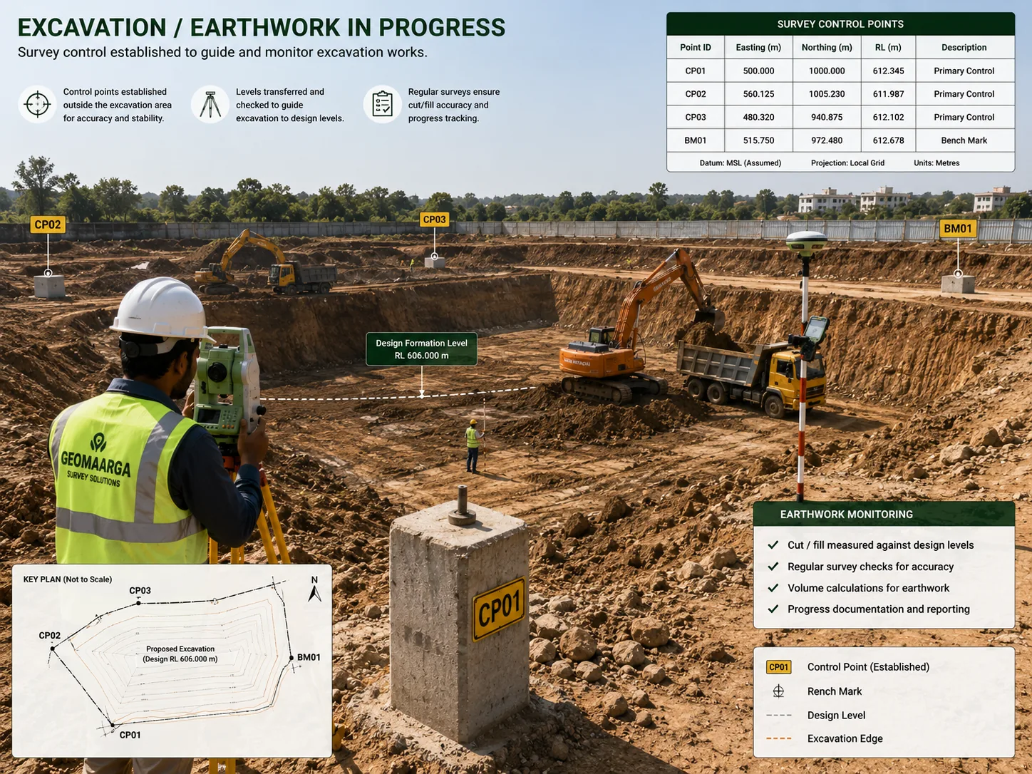
- Site Level Survey — earthwork volumes along the route
- Infrastructure Survey — highway and corridor projects
- All construction survey services
How we work
How we set out a road
-
Read the alignment
Horizontal and vertical geometry taken from the design, chainages confirmed, and tie-in points to existing roads checked against the measured ground.
-
Establish control along the route
Reference points set along the length and closed, so the far end of the road is as accurate as the start rather than accumulating error along it.
-
Peg the centreline
Centreline set out at chainage, with intervals closed up through curves according to the radius, and offset pegs placed clear of the working width.
-
Set formation levels
Level pegs at chainage with cross-section levels across the width, and camber marked, so the earthwork is cut and filled to a reference.
-
Set kerbs and drainage
Kerb lines set as offsets with levels along the top, and gully positions and invert levels set from the same control.
-
Check as layers go down
Where included, levels checked as each pavement layer is built up, so thickness and fall are confirmed rather than assumed.
Questions
Road alignment FAQs
Broadly, yes — road alignment, centre line marking and road marking are all used for this work on site. The centreline is the spine of it: once that is set at chainage, everything else — edges, kerbs, camber, formation levels — is measured as an offset from it. Ask for whichever term you are used to; we will know what you mean.
Chainage is distance measured along the centreline from a fixed start point, so a position on the road can be described as a single number rather than a coordinate. It matters because it gives everyone on site one shared language — the design, the level sheet, the earthwork claim and the site instruction all refer to the same chainage, and nobody has to work out which part of the road is meant.
By computing coordinates along the curve from its design geometry and setting out points at regular chainage intervals, closer together on a tight radius than on a gentle one. A curve marked as a series of straight chords between widely spaced pegs looks acceptable on the ground and is wrong at every point between them. How close the intervals need to be is decided by the radius, not by convenience.
Yes, and on a road the levels are usually the harder part. Formation level is set at chainage with cross-section pegs so the machine has a reference, camber or crossfall is marked so the surface drains, and layer thicknesses can be checked as the pavement is built up. A road built on line but not to level does not drain, and that is the failure that shows up in the first monsoon.
Yes. Kerb lines are set as offsets from the centreline with levels along the top, so the kerb is laid to a line and a grade rather than followed by eye. Road drainage — gully positions, invert levels, and the falls between them — is set out from the same control, which keeps the road surface and the drainage that serves it consistent with each other.
This page covers internal, access and layout roads within a development. Highway and corridor projects — longer alignments, multiple structures, tie-ins to existing carriageway — are handled as infrastructure survey, where control is established along the whole route rather than from a single site framework. Tell us the length and we will say which approach fits.