
Infrastructure Survey
Highway survey — the corridor measured end to end
Strip survey, longitudinal sections and cross sections at chainage for new roads, widening and rehabilitation. Tied to control that runs the whole length, so the far end is as accurate as the start.
On site the deliverables are usually called the L-section and X-sections, from a strip survey.

What you get
Agreed in the quotation before we mobilise. A highway survey normally delivers:
- Strip survey plan in DWG and DXF, layered, covering the agreed corridor width
- Longitudinal section along the centreline, plotted against chainage
- Cross sections at the agreed interval, closing up on curves and at structures
- Existing carriageway edges, crown levels and shoulder levels
- Culverts, drains, chambers and structures located, with invert levels where accessible
- Control point record along the route, so later stages tie into the same framework
- Coordinate and level schedules in CSV or Excel, plus the survey report
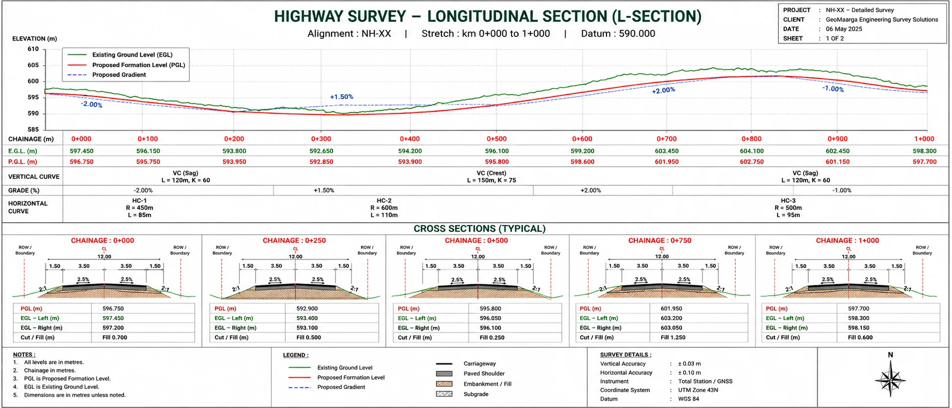
Strip survey, L-section, cross sections
Three deliverables that together are what a highway design gets drawn on.
- Strip survey — a mapped band of ground along the route, typically the carriageway plus an agreed width either side. Everything within it is located: edges, drains, culverts, poles, boundaries, structures.
- L-section — the longitudinal profile along the centreline, showing how ground level rises and falls against chainage. This is what the vertical alignment is designed on.
- Cross sections — profiles cut across the route at intervals, showing the shape from one side to the other. Earthwork quantities are computed from these.
Cross section interval is commonly 20 to 50 m on straights, closing up on curves, at structures and at junctions. It is agreed before mobilising because it drives both the cost and how well the computed earthwork matches what actually gets excavated.
Over kilometres, a traverse accumulates error. So we do not use one.
On a site, a closed traverse around the boundary is ideal — errors are distributed around a loop that returns to its start. A corridor has no loop. It runs away from where it began, and error in a traverse grows with the distance carried.
So control on a highway project is established by static satellite observation at intervals along the route, each point fixed independently rather than carried forward from the last. Total station work then fills in detail between those control points, over short distances where a traverse behaves well.
The result is that chainage 8000 is as accurate as chainage 0 — which is not true of a survey traversed from one end.
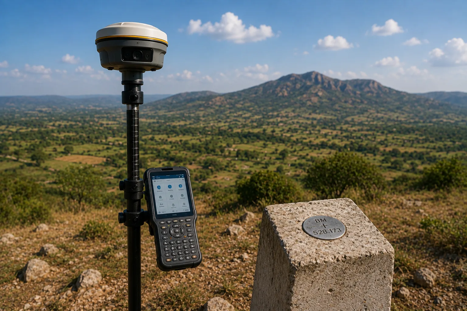
Working on a road that is carrying traffic
Most rehabilitation and widening work is surveyed on a live carriageway. It changes how the survey is done rather than whether it can be done.
- Reflectorless measurement wherever it avoids putting someone in the running lane
- Work planned around traffic — lighter periods used for the parts that need road presence
- Control set off the carriageway, so occupying it does not mean standing in traffic
- Safety measures agreed with you in advance, including any permissions or traffic management you need to arrange
Tell us the traffic conditions with the enquiry. It affects the method, the programme and the price, and it is better established before mobilising than discovered on the first morning.
Accuracy you can expect
| Measurement | Accuracy | Notes |
|---|---|---|
| Route control, static post-processed | ±2.5 mm + 0.5 ppm | Independent fixes along the corridor |
| Detail pickup, RTK | ±8 mm + 1 ppm | Open carriageway and shoulders |
| Detail pickup, total station | ±10–20 mm | Under trees, beside structures, in cuttings |
| Levels along the section | ±5–10 mm | Closed level runs between control points |
Figures are typical achievable tolerances for survey-grade equipment under reasonable field conditions, not a contractual guarantee. The tolerance your project requires is set by the specification you are working to — tell us which one and we will confirm our method meets it before you appoint us.
When you need this
- At feasibility, to establish what the ground along a proposed route does
- Before detailed design of a new road or realignment
- Before widening, so the existing carriageway is measured rather than assumed
- Before rehabilitation, to establish existing levels and surface condition geometry
- For earthwork quantity estimation from measured cross sections
- Where land acquisition needs the corridor and boundaries defined
Typical applications
- New road alignmentStrip survey and sections along a proposed route for design
- Widening projectsExisting carriageway measured, plus corridor width for the new formation
- Rehabilitation and resurfacingExisting levels and geometry recorded before overlay design
- Junction improvementDetailed survey where geometry and levels are constrained
- Earthwork estimationCross sections at interval for cut and fill quantities
- Land acquisition supportCorridor and boundary detail along the affected length
Related reading
Corridor work uses both methods deliberately — satellite positioning to carry control along the route without accumulating error, total station for detail where the sky is obstructed.
- GPS vs DGPS — and why the ppm term matters over distance
- Total station or DGPS — how we choose the method
- Why satellite levels are not sea levels
Related services
- Railway Survey — corridor work to railway tolerances
- Pipeline Survey — route profile and crossings
- Utility Corridor Survey — existing services within the corridor
- Road Alignment — setting the design out on the ground
- DGPS Survey — the control method behind corridor work
- Drone Survey — corridor mapping over long or difficult ground
- All infrastructure survey services
How we work
How we survey a highway corridor
-
Agree corridor and intervals
Strip width, cross section interval, chainage origin and datum settled with your design team before mobilising.
-
Establish control along the route
Static satellite observation fixing control points independently at intervals, so accuracy does not degrade with distance from the start.
-
Tie levels to benchmarks
Levels carried by closed runs between control points and checked against reachable benchmarks, with the datum stated.
-
Pick up the strip
Carriageway, shoulders, drains, culverts, structures and boundaries recorded across the agreed width, by RTK in the open and total station where obstructed.
-
Take the sections
Cross sections cut at chainage, closing up on curves and at structures, and the longitudinal section observed along the centreline.
-
Process, plot and issue
Strip plan, L-section and cross section sheets drawn to your standard, with schedules and the control record issued alongside.
Questions
Highway survey FAQs
A strip survey maps a band of ground along the route — typically the carriageway plus a width either side agreed with your designer. The L-section, or longitudinal section, is a profile along the centreline showing how ground level rises and falls with chainage. Cross sections are profiles cut across the route at intervals, showing the shape from one side to the other. Together they are what a highway design is drawn on.
It depends on the design. Rehabilitation of an existing carriageway may need only a narrow band; a widening or realignment needs enough width either side to accommodate the new formation, drainage and land acquisition line. Tell us what is being designed and we will recommend the width, because surveying more than the design needs costs money and surveying less means going back.
Commonly every 20 to 50 m on straight sections, closing up on curves, at structures, at junctions and wherever the ground changes shape sharply. The interval is agreed before mobilising because it drives both the cost and how usable the sections are — too wide and the earthwork quantities computed from them will not match what is actually excavated.
By not traversing the whole length. Error in a traverse accumulates with distance, so on a long corridor control is established by static satellite observation at intervals along the route, each point fixed independently rather than carried forward from the last. Total station work then fills in detail between those control points. That way the far end of the project is as accurate as the start.
Yes, and most rehabilitation and widening work is exactly that. It changes how the survey is done rather than whether it can be — reflectorless measurement to avoid standing in the carriageway, work planned around traffic patterns, and safety measures agreed with you in advance. Tell us the traffic conditions with the enquiry so the method and the programme reflect them.
We record what is visible and measurable — culverts, drains, chambers, poles, utility markers, structures, and the existing carriageway edges and levels. Buried services between visible points are a separate utility detection exercise, which we can arrange. On a corridor project this matters more than on a site, because a service discovered during construction can hold up an entire stretch. See utility corridor survey.