
Datums and levels
Why satellite levels are not sea levels — and what to check on your drawing
A GNSS receiver reports height above a mathematical model of the earth, not height above the sea. In India the difference runs to tens of metres. If your drawing does not say which one it used, you cannot design drainage from it.
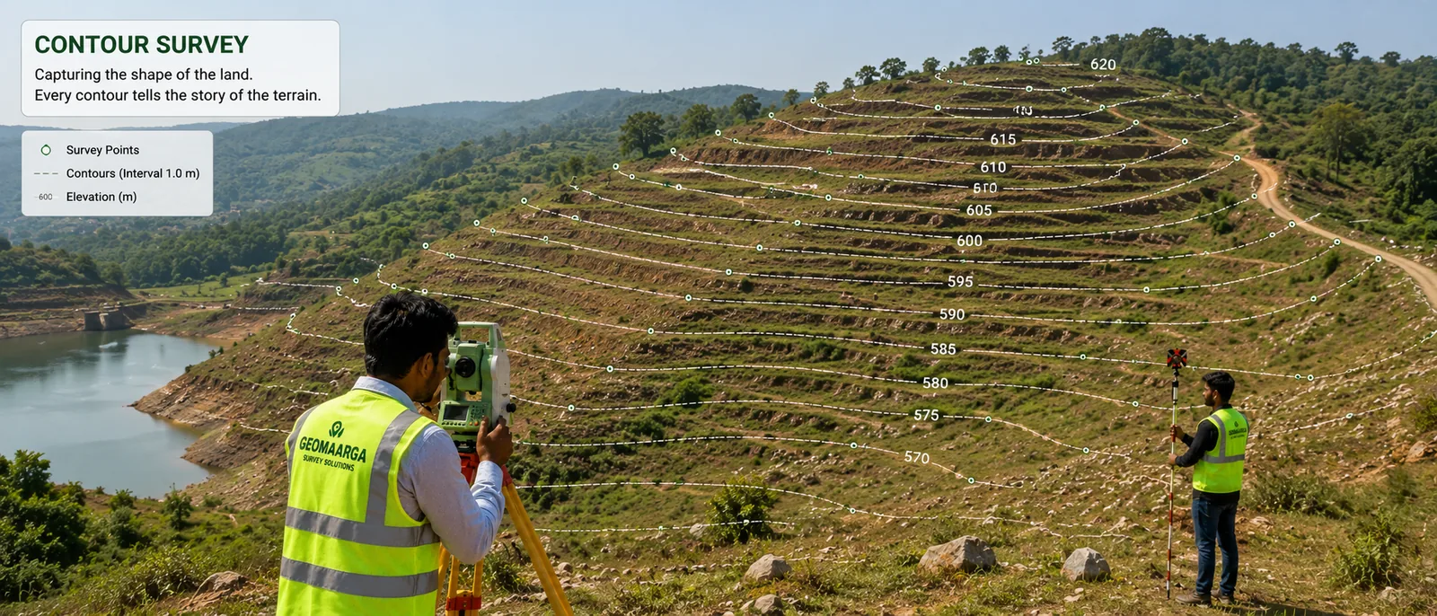
Two different ideas of "sea level"
Height has to be measured from something. Two candidate surfaces are in everyday use, and they are not the same shape.
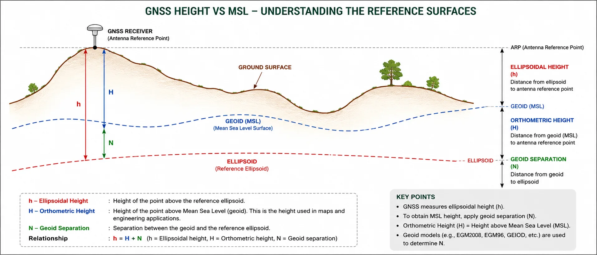
The ellipsoid is a smooth mathematical figure — a sphere squashed slightly at the poles — chosen to fit the earth's overall shape as closely as a simple formula can. It has no physical existence. Its virtue is that it is perfectly regular, so a receiver can compute a height against it with pure geometry. WGS 84, the system underlying GPS, uses one of these.
The geoid is the surface that gravity actually produces: the level the sea would settle at if it could flow freely everywhere, with no tides, currents or wind. It is lumpy, because the earth's mass is unevenly distributed — dense rock beneath you pulls the surface up, a deep sedimentary basin lets it sag. Mountains, notably, have a lot of mass.
Mean sea level, and therefore every level on every engineering drawing that says MSL, is referenced to the geoid.
The gap between them
The vertical separation between geoid and ellipsoid at any place is called the geoid undulation or geoid height. It is not a small correction and it is not constant.
Globally it ranges from roughly −105 m to +85 m. Across the Indian subcontinent it varies substantially from place to place — the Indian Ocean south of the peninsula holds one of the largest negative anomalies on earth, while the Himalayan mass pulls the geoid up in the north. The practical point for a surveyor in Karnataka is simply this: the number is tens of metres, and it changes as you move.
The relationship is straightforward arithmetic:
Orthometric height = ellipsoidal height − geoid height
The level you want on the drawing — orthometric height, effectively MSL — is what the receiver reports minus the geoid separation at that place. Get the geoid separation wrong, or forget it entirely, and every level on the drawing is wrong by the same large amount.
Which is, in a way, the dangerous case: a uniform error looks internally consistent. Contours still make sense relative to each other. It only bites when the drawing has to agree with something outside itself — a road level, a trunk sewer invert, a neighbouring plot, a flood datum.
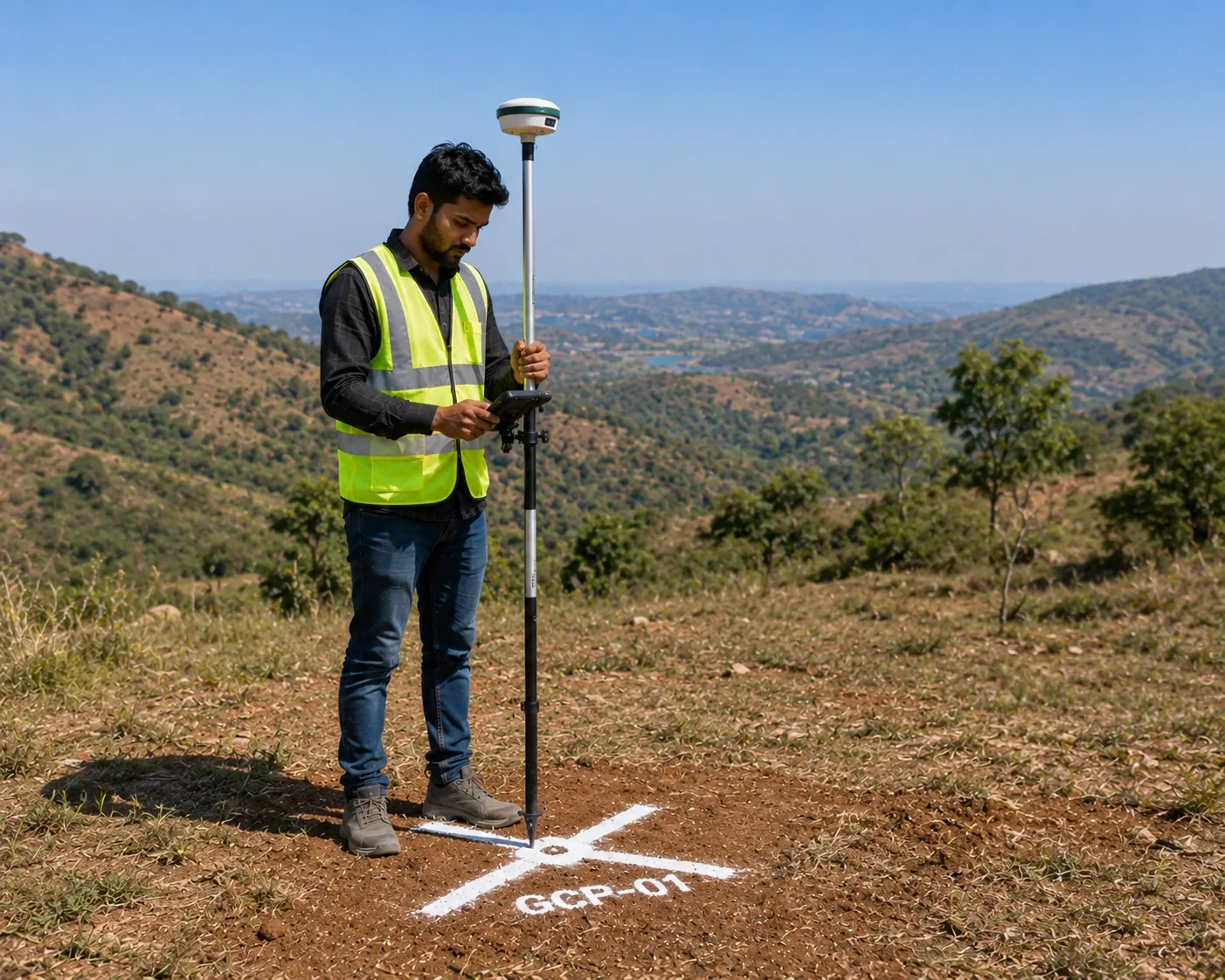
How the conversion is actually done
Two routes, usually used together.
A geoid model. Global models such as the EGM series give the geoid separation for any latitude and longitude, and survey software applies them automatically. This is convenient and generally good, but it is a model — its accuracy in any particular locality depends on how well the underlying gravity data covered that area.
A tie to a levelled benchmark. The stronger method where one is available. Survey of India maintains GTS benchmarks whose MSL levels were established by precise spirit levelling carried over long distances. Observe the benchmark, compare the model's answer against its published level, and you have a local correction that accounts for whatever the model is getting wrong in your area.
Where no benchmark is within practical reach, the honest course is an assumed datum — pick a stable point on site, call it a round number, and label it unmistakably as assumed. A clearly labelled assumed datum is safe. An unlabelled one that a later engineer mistakes for MSL is not.
What to check on any drawing you receive
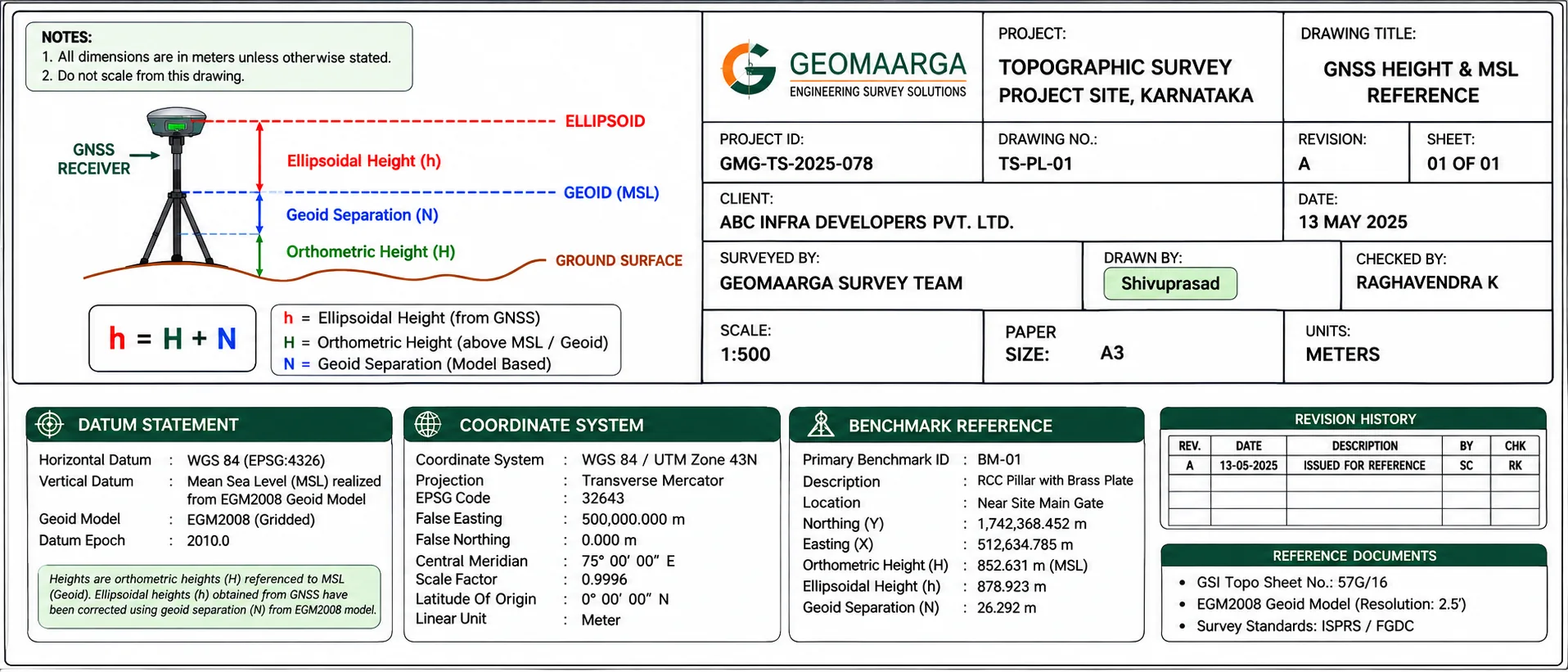
You do not need to be a surveyor to audit this. Look for four things.
- Is the vertical datum stated at all? Somewhere on the sheet it should say MSL, or reduced level to a named benchmark, or assumed datum. If nothing is stated, the levels are unusable outside the drawing.
- If MSL, which benchmark? A benchmark number and its published value, so the tie can be checked or repeated.
- If assumed, is it labelled as such? And is the reference point described well enough to find again — not "corner of site" but a specific, described, ideally photographed mark.
- Is the horizontal system stated too? Coordinate system and projection, for the same reason.
A drawing that answers all four can be tied to other work years later. One that answers none is a picture, not a survey.
Why this causes real problems
The failure is rarely dramatic at the time. It surfaces later:
- A drainage design that will not connect to the trunk sewer, because the invert levels were on different datums.
- Earthwork volumes computed against a surface that sits systematically high or low, so the priced cut and fill are both wrong.
- A finished floor level set from a survey that disagrees with the abutting road, discovered when the approach ramp does not work.
- Two surveys of adjacent parcels that cannot be merged, because one used MSL and the other an unlabelled assumed datum.
Every one of these is cheap to prevent and expensive to discover. It costs nothing to state a datum on a drawing, which is why its absence tells you something about the survey.