
Infrastructure Survey
Pipeline survey — the profile that decides where the fittings go
Route profile, crossings and existing service detail for water, sewerage and process pipelines. Plus the as-laid record taken while the trench is still open, because after backfill nobody can measure it again.
Also called a pipeline route survey, trench survey or simply the L-section.
What you get
Agreed in the quotation before we mobilise. A pipeline survey normally delivers:
- Longitudinal section along the route, plotted against chainage
- Corridor plan to the agreed width, layered in DWG and DXF
- High and low points identified, where air valves and washouts will be needed
- Crossings surveyed in detail — roads, railways, rivers, canals, other services
- Existing visible services located, with invert levels where chambers can be opened
- Setting out of centreline, trench width and invert level where included
- As-laid survey before backfill, with coordinate and level schedules

Air collects at the top. Silt collects at the bottom.
A pipeline follows the ground, so it rises and falls. Air gathers at every high point and has to be released, which is where air valves go. Water and sediment gather at every low point, which is where washouts go.
The profile is what tells the designer where those points are. If an undulation is missing from the survey, no valve is designed for it — and the pipeline gets an air lock that throttles the flow, or a silt trap that nobody can locate once the pipe is buried.
Which is why the route is walked and the rises and falls recorded, not sampled at a convenient interval and smoothed between.
Gravity mains need canal-grade levelling
There are two kinds of pipeline and they need different levels of precision.
A pressure main is pushed by a pump. It can climb, and moderate level error is tolerable because the pump provides the head.
A gravity main — a sewer, or a gravity water main — flows only because it falls, often at a very shallow gradient. Here the level survey has to be precise levelling with closed runs, the same standard we apply on canal work. A sewer laid slightly against its intended fall does not work at all, and unlike almost anything else on a construction site, it cannot be adjusted afterwards.
Tell us which kind it is with the enquiry. It changes the method, the time on site and the price.
Existing services are the main risk
A building sits in one place. A pipeline trench travels, which gives it far more opportunities to hit something that was already there.
We record everything visible and measurable along the corridor — chambers, valve covers, marker posts, poles, exposed services — and take invert levels where a chamber can be safely opened. Tracing buried services between those visible points needs detection equipment, which we can arrange when the project warrants it.
What we will not do is draw an assumed service route as though it had been measured. On a pipeline that is not a small dishonesty — it is the line somebody digs along.
Crossings drive design and cost
- Roads and railways — surface levels and structures, since the pipe is usually pushed or bored beneath rather than cut through
- Rivers, canals and nalas — bank and bed levels, because the pipe has to pass below scour depth
- Other pipelines and cables — located wherever they can be, because a clash at a crossing is the most expensive kind to resolve
- Boundaries and land parcels — where the route crosses ownership, for way-leave and compensation
The as-laid survey happens before backfill
This is the point on this page most worth acting on.
Once the pipe is covered, its line and invert levels cannot be measured directly ever again. Anything drawn afterwards is inference from the chambers at each end — a straight line between two known points, through ground where the pipe may well have gone around something.
An as-laid record taken in the open trench is the only version worth having. It is what a maintenance crew will rely on in ten years when they need to find the pipe, and what a future contractor will check before digging near it.
Accuracy you can expect
| Measurement | Accuracy | Notes |
|---|---|---|
| Invert levels, gravity main | ±5–10 mm | Precise levelling, closed runs between benchmarks |
| Route control, static post-processed | ±2.5 mm + 0.5 ppm | Independent fixes along the alignment |
| Route profile and detail, RTK | ±8 mm + 1 ppm | Open ground along the corridor |
| Detail in built-up sections | ±10–20 mm | Total station, where satellite reception fails |
Figures are typical achievable tolerances for survey-grade equipment under reasonable field conditions, not a contractual guarantee. Satellite levels are not used for gravity main inverts — the required precision is finer than satellite positioning delivers reliably.
When you need this
- At route selection, to compare alignments on measured ground
- Before detailed design, so fittings are placed against a real profile
- Before trenching, to set out centreline, width and invert level
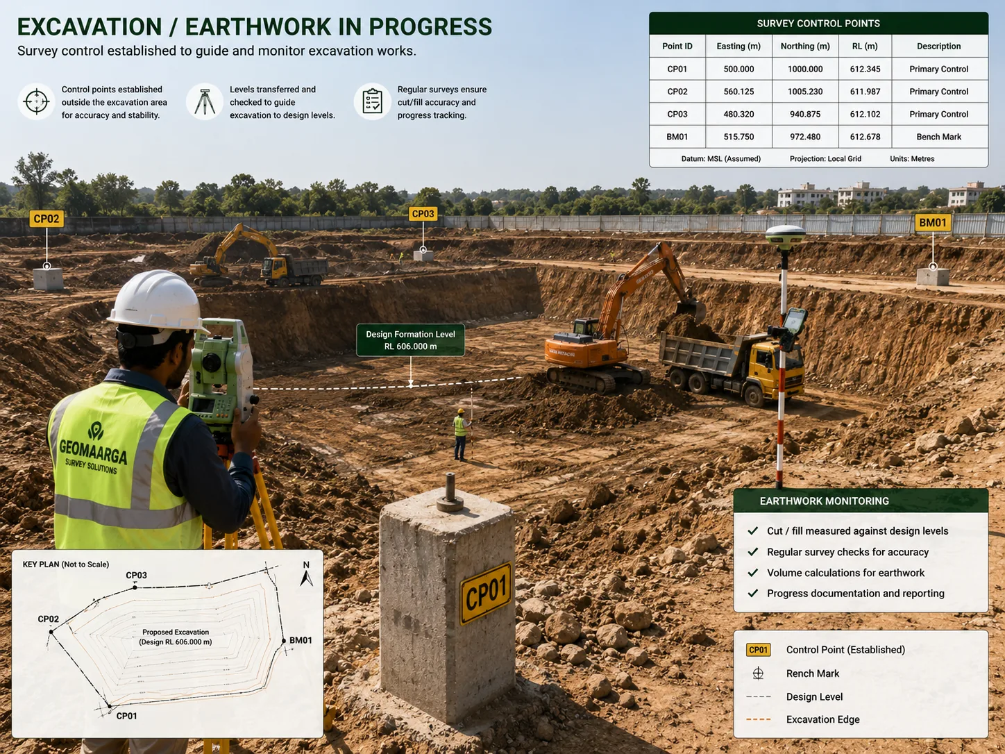
- Through the excavation, to control invert depth as the dig proceeds
- Before backfill, for the as-laid record
- When an existing main has to be located, or a new one designed to avoid it
Typical applications
- Water supply mainsRoute profile, air valve and washout points, crossings
- Sewerage and gravity mainsPrecise invert levels where the gradient is the whole design
- Process and industrial pipelinesRoutes through plant, with clash detail against existing services
- Layout and township networksInternal water and sewer networks within a development
- Trenchless crossingsEntry and exit levels for pushing or boring beneath roads and rail
- As-laid recordingLine and invert measured in the open trench before backfill
Related reading
Pipeline work combines satellite control along the route with precise levelling for inverts. The datum matters as much as it does on canal work, because a new main usually has to connect to an existing network.
- Why satellite levels are not sea levels
- GPS vs DGPS — and why the ppm term matters over distance
- Total station or DGPS — how we choose the method
Related services
- Canal Survey — the same precise levelling, in an open channel
- Utility Corridor Survey — mapping services in a shared corridor
- Highway Survey — corridor survey for road projects
- Transmission Line Survey — route profile above ground
- As-Built Survey — recording what was constructed
- Existing Feature Mapping — visible services on a site
- All infrastructure survey services
How we work
How we survey a pipeline route
-
Establish datum and control
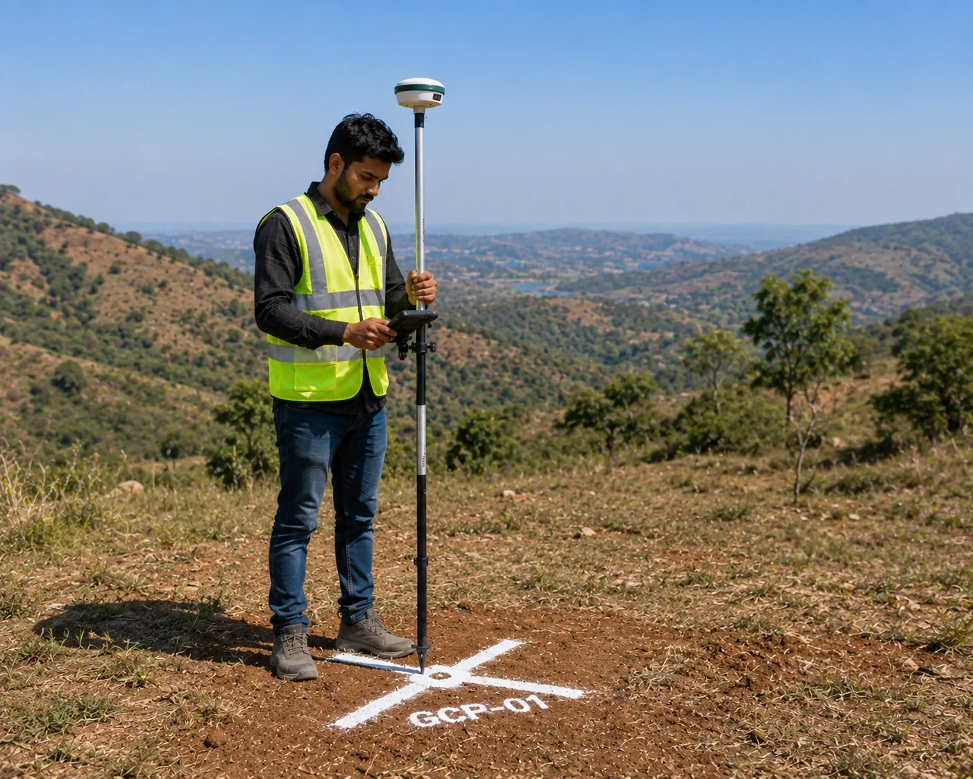
Benchmarks located so the new main ties to the existing network, and control fixed independently along the route by static observation.
-
Profile the route
Ground recorded along the alignment with every rise and fall captured, because those are where the air valves and washouts will go.
-
Record services and crossings
Visible services located with invert levels where chambers open safely, and every crossing surveyed in its own right.
-
Set out the trench
Centreline pegged at chainage with offsets clear of the dig, trench width marked, and invert level controlled as excavation proceeds.
-
Record as laid, open trench
Pipe line and invert levels measured before backfill, with photographs — the only stage at which this can be done truthfully.
-
Plot and issue
L-section, corridor plan and as-laid record issued with schedules and the datum stated on every sheet.
Questions
Pipeline survey FAQs
Because the profile decides where the fittings go. Air collects at high points and has to be released, so air valves are placed there; water and sediment collect at low points, so washouts go there. If an undulation is missing from the profile, no valve is designed for it, and the pipeline gets an air lock or a silt trap that nobody can find once it is buried.
Yes, and the difference is precision. A pressure main is pushed by a pump, so moderate level error is tolerable. A gravity main — a sewer or a gravity water main — flows only because it falls, often at a very shallow gradient, so the level survey has to be precise levelling with closed runs. A sewer laid slightly against its intended fall does not work at all, and it cannot be adjusted afterwards.
We record everything visible and measurable — chambers, valve covers, marker posts, poles, and any exposed service — and take invert levels where a chamber can be safely opened. Tracing buried services between those points needs detection equipment, which we can arrange. On a pipeline this matters more than on most jobs, because the trench follows a line rather than sitting in one place, so it has many more opportunities to hit something.
Crossings usually drive both the design and the cost. Roads and railways are recorded with surface levels and structures, since the pipeline is normally pushed or bored beneath them. Rivers, canals and nalas get bank and bed levels, because the pipe has to pass below the scour depth. Other pipelines and cables are located where they can be, because a clash at a crossing is the most expensive kind.
Before backfill, with the trench still open. Once the pipe is covered, its line and invert levels cannot be measured directly again — anything drawn later is inference from the chambers at each end. An as-laid record taken in the open trench is the only version worth having, and it is what a future engineer or maintenance crew will rely on when they need to find the pipe.
Yes. Centreline pegged at chainage with offset pegs clear of the excavation, trench width marked, and invert level controlled as the dig proceeds so the pipe is bedded at the designed depth rather than wherever the machine stopped. On a gravity main that level control through the excavation is the difference between a sewer that flows and one that does not.